Wednesday, May 14, 2014

Two way 12 LED running lights using CD4017 and NE555

This Two way LED running lights to use for beautiful, this circuit uses 12 LED lamps, arranged in 2 rows, each row of 6 leds. A green one and a red one, alternatively. use a different color for this.
Technical information
-The power supply of 6-12 VDC.
-Power consumption is about 12 mA maximum
-Have the speed of the flashing.
-PCB dimensions: 2.80 x 1.77 inchs.
How it works
This circuit have 2 IC, IC1-555 is frequency generator, by this frequency can adjust at 10K-potentiometer output of IC1 through R-100 ohms in to pin 14 of IC-4017. The IC-4017 is Decade counter with 10 decoded outputs IC IC.
Two way 12 LED running lights using CD4017 and NE555
In Figure 1 is Two way 12 LED running lights using CD4017 and NE555.
Which its output glowing will slide down each position, by begin from output at 1 is pin 3, 2, 4, 7, 10, 1, 5, 6, 9 and 11 in sequence.
When it to pin 11 the output light will back to pin 3 and continue to glow in sequence each step, by the signal from IC-555 in circuit. Which we can set output at 6 position then backward glow, by notice at the IC output pin as LED can reverse run. The 1N4148-Diodes to protects voltage from output to same LED point.
How to builds.
The circuit assembling is shown in Figure 2 should begin low to high parts sequence, for Beautiful and simple. By begin with diode, resistors and higher. And the parts have different polarity such as Diode, Electrolytic Capacitors and transistors etc.
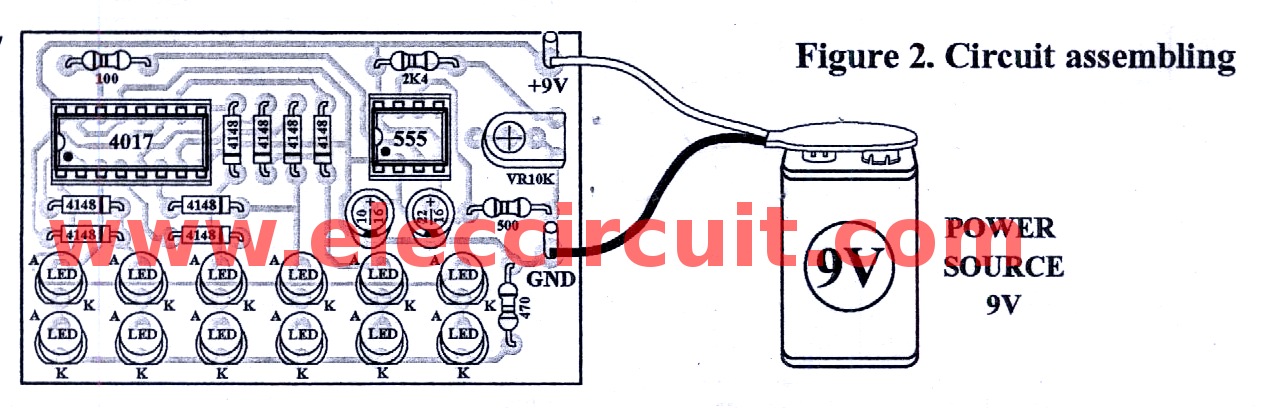
The components layout on PCB
Figure 2 The circuit assembling as components layout on PCB
Testing
To apply a power supply size 9-volts to circuit will see LED glow continue step to step run go and back. And can adjust speed up by adjust at 10K-potentiometer.
Application
This circuit uses power from 9-12-volts Therefore can install in the car using voltage 12-volts.
The component list.
Resistors
R1—————2.4K
R2—————500 ohm
R3—————100 ohm
R4—————470 ohm
Trimmer Potentiometer
VR1————-10K or 103
Electrolytic Capacttors
C1—————22uF
C2—————10uF
IC1————–NE555 Timer IC
IC2————–CD4017- Decade counter with 10 decoded outputs IC
Diodes
D1-D8———–1N4148__ 75V 150mA Diodes

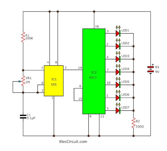
 

7 Led light running adjust speed by 4017 and 555


The led light running circuit generally can not adjust the speed of running. Cause dull monotony. Resulting in an idea to build this circuit up. This circuit can adjust the speed of the led light as needed. Makes this circuit can be used more versatile.
Operation of the circuit is divided into two parts: frequency generators. And the display. By the frequency generator IC1 contains a number Ic timer circuit 555 and frequency generator. Defined by the R1, VR1 and C1 will be the output signal at pin 3 of IC1 sent to display section.
In display section consists of IC2, a number CD4017 IC Counter circuit is displayed by the volt at pin 3, 2, 4, 7, 10, 1 and 5, respectively, each pin. The speed depends on the frequency count obtained from pin 14 of IC2, which we can adjust VR1 adjusts the frequency from the frequency generator part.
7-Led-light-running-adjust-speed-by-4017-and-555

LED Chaser by IC 4017 + IC 555

If you want to build a 10 LED Chaser circuit we suggest this circuit first. It uses popular IC is a simple and affordable IC-4017_decade counter and IC-555.
As Figure 1 is LED chaser circuit whicn The CD4017 act as LED driver in 10 output, by LED will glow only one in a rapid sequence. And control to speed with VR1 which is setting frequency output of a basic astable or free-running pulse generator with IC-555 as main.
The detail is other see in circuit picture better.
 LED Chaser by IC 4017 + IC 555Circuit LED Chaser by IC 4017 + IC 555
This circuit is working in below.

When we experiment them as well next step we come to make…
 
https://www.youtube.com/watch?feature=player_embedded&v=Utm02VZLCh0

Electronic Cricket Match Game

This electronic cricket is a present for Kids. This simple battery powered circuit can be used to play Cricket Match with your friends. Each LED in the circuit indicates various status of the cricket match like Sixer, Run out, Catch etc.
The Circuit uses two ICs ,one in the Astable mode and the second in the display driver mode. IC1 is wired as an Astable Multivibrator with the timing elements R1, R2 and C1. With the shown values of these components very fast output pulses are generated from the Astable. Output from IC1 passes into the input of IC2 which is the popular Johnson Decade counter CD4017. It has 10 outputs. Of these 8 outputs are used. Output 9 ( pin9) is tied to the reset pin 15 to repeat the cycle. When the input pin 14 of IC2 gets low to high pluses, its output turns high one by one. Resistor R3 keeps the input of IC2 low in stand by state to avoid false indications.

Electronic Cricket Circuit Diagram


When the Push Switch S1 is pressed momentarily, the Astable operates and all the LEDs run very fast sequentially. When S1 is released, any one of the LED stands lit which indicates the status of the match. For example, if LED D7 remains lit, it indicates Sixer and if LED 8 remains lit, it indicates Catch out.
Label each LED for its status as shown in the diagram. Pressing of S1 simulates Bowling and Running LEDs indicates running of Batsman.

LED Chaser Circuit

This is the circuit of a simple LED chaser. The LEDs lights one by one for a period of 1second and the cycle repeats giving the running light appearance. The circuit uses two ICs (one is 555) to drive the LEDs.

IC1 (NE555) is the popular timer IC wired in the Astable Multivibrator mode. Resistors R1, VR1 and capacitor C1 act as the timing components and the output pulses are available from the output pin 3 of IC1. These pulses are given to the input pin 14 of the Johnson decade counter IC CD4017. Out of the 10 outputs of IC2, eight outputs are used to drive the LEDs. The ninth output pin 9 is connected to the reset pin 15 to stop the counting. So that the cycle repeats. With the value of C1, each LED remains on for 1second. When one LED turns off, the second on turns on. This cycle repeats giving the running light appearance. Resistor R3 keeps the input pin 14 of IC2 low after each pulse.VR1 adjusts the speed of LED chasing.
 

Saturday, May 10, 2014

Three led flasher by 3 transistor astable multivibrator

Three led flasher by 3 transistor astable multivibrator 

The Flash rate of LED1-LED3 in each frequencies output are easily changed simply by changing one, or three of the timing capacitors (C1,C2,C3) which each capacitors not need same capacitances.
The Resistors-10K are used to bias transistor conducting.
And we insert VR1-10K-potentiometer to control base current of transistors which importance them are used to simply adjusts the flash rate.
And each the 470 ohms resistors is used to control current flow through or limits current to each LEDs.
We assemble all components into the breadboard as video below.
We will see that, the LEDs alternately flash ON and OFF about once per second, always two LED will glow each time.
The components List
Q1-Q3____CS9013__500mA 30V NPN transistor______= 3 pcs.
C1-C3____47uF 35V Electrolyte capacitors__________= 3 pcs.
VR1___10K (B) Potentiometer single ________________ = 1 pcs.
R4-R6_____470 ohms ___1/4watts resistors___________ = 3 pcs.
R1-R3______10K ____1/4 watts Resistors____________ = 3 pcs.
LED1-LED3___LED as you wants____________________ = 3 pcs.
PCB or bread board.


http://www.eleccircuit.com/wp-content/uploads/2008/04/4017-led-pattern-flasher.jpg